

Bench for testing algorithms for control of electrical power grids
The experimental complex is a unique installation for the study and research of power grid control systems. This complex allows you to explore any network management algorithms in normal operation and emergency situations associated with a sudden change in network load.
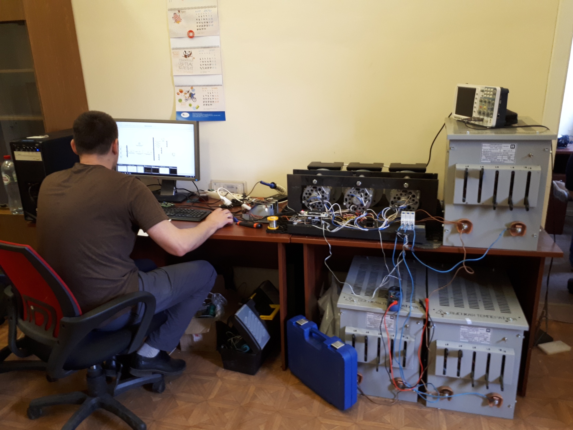
The principle of operation of the experimental complex
Functional diagram of the experimental complex:
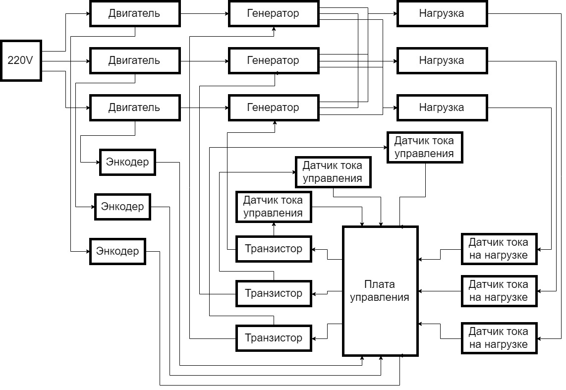
Control systems are three electric generators (model 371.3701), each of which has:
Direct mechanical connection with an electric motor (model 5AIE 71 B2) to set the generator in motion. The excitation winding of the rotor to control the energy generated by the generator. 3 phase output current for unloading. The role of the source of mechanical action on the generators is played by AC electric motors powered by a 220-volt network. The shaft of the motor and the generator is connected by a flexible coupling, on which a disk is fixed for the operation of an optical encoder (model FC-03). The encoder is used to obtain data on the rotation speed of the generator shaft. The received data is transferred directly to the control board (model STM32).
Ballast rheostats (model RB - 302) and inductors from welding machines are used to relieve the load of generators. In this case, the same phases from 3 generators are connected and connected to 3 different load devices. The second terminal of the load device is connected to a common "0" combined with three generators.
Data on the current flowing through the load is provided by 3 AC sensors (model ACS712) connected each to the corresponding load, the signal from the sensors goes to the control board.
The control board consists of two devices connected to each other via UART. The role of the computer on which the control signals are calculated is performed by a personal computer with the MATLAB/Simulink software package installed. The second STM32 board is designed to collect information from sensors, exchange information with a personal computer, and generate a PWM transistor control signal. MOSFET transistors ensure the passage of the required current through the control winding of the generator rotor. They have an external power supply of 12 volts. To adjust the operation of the transistors, current sensors are used in the excitation winding circuit, the signal from which goes to the control board.
List of the main equipment of the experimental complex, containing the name and main characteristics of the devices
- Generator 371.3701. Maximum power 770 W, rated voltage 14 V, maximum current 55 A, rotor speed corresponding to the rated voltage under load - 2000 rpm, 14 V, 35 A.
- Electric motor 5AIE 71 V2 (asynchronous). Power 750 W, rated rotation speed 3000 rpm.
- Speed sensor FC-03 based on LM393 chip. Encoder output interface or type: digital TTL. Field winding current sensor ACS712 20 A. Load current sensor linear AC/DC 57A, CSLA1CD. The maximum measurement current is 57 A. load devices.
- Ballast rheostat "RB-302", which allows you to dissipate up to 315 A at a voltage of 75 V. On this rheostat, the load is switched on in steps, using 6 knife switches, each of which is responsible for its own load circuit. Inductive coils are used to simulate an inductive load, designed for welding machines with a current carrying capacity of up to 300 A.
- Power supplies. To connect the electronics, a minimum constant voltage of 12 V is required (a 200-400 W computer power supply is used). The stand uses a 5V FSPGroupATX-350PNR power supply. A Faraday 100W/24V power supply is used for the excitation winding on each generator.
- Computer on x86 architecture. This device is required to run and use Matlab/Simulink. Debug board based on Atmega and STM microcontrollers. This solution completely covers the required parameters, and also allows you to connect a USB-microUSB cable to a PC and transfer data directly using UART
List of performed typical works
- Testing algorithms for managing a network of electric generators in normal network operation
- Testing algorithms for controlling a network of electric generators with a sudden change in active and reactive loads in the network.
- Debugging of power grid control algorithms.
- Study of the operation of a network of electric generators with constant and variable load in the network.
List of applied measurement techniques
- Measurement, processing of received signals, visualization and control is carried out in real time using computerized tools and involving licensed software MatLab Simulink RealTime 2015.
- The minimum achievable time slicing period is 0.5 sec.
- Measuring the angles of rotation of the rotor - 3 measurements per full revolution.
- Measurement of load currents, nominal interval 40-50 A.There are 6 switches on each of the three phases, stepwise changing the load resistance.
Stand uniqueness degree
- Online monitoring of all parameters in the network.
- Online control of electrical generators.
- Research of any existing control algorithms.
- The study of new algorithms for managing the electric power network.
- Programming control algorithms in the Matlab software environment.
- Designing control algorithms in the form of block diagrams in the Matlab/Simulink software environment.